Mikrotron camera acts as remote vibration sensor in experimental high-speed vision platform
05/11/2025
Vibration monitoring (VM) is widely used in mechanical analysis, especially for machinery with reciprocating and rotating parts, including engines, bearings, gearboxes and motors. Monitoring vibration data helps machine operators to identify potential failure points early on, thereby reducing maintenance and downtime. Likewise, VM is a valuable tool in monitoring the structural health of civil infrastructures. An example of this would be surveying bridges for fatigue due to traffic or environmental loads.
Traditionally, VM has been conducted using various types of contact sensor, such as accelerometers or piezoelectric sensors, that measure displacement, velocity and acceleration. Both accelerometers and piezoelectric sensors are effective for measuring vibrations; however, they have the following limitations:
Requirements for physical contact to the surface being monitored can be challenging for moving, rotating or inaccessible components.
Each sensor monitors vibrations at a specific point, requiring multiple sensors for large or complex structures.
Harsh environments such as extreme temperatures, humidity or corrosive conditions can degrade sensor performance or lifespan.
Sensor maintenance, such as recalibration or replacement, can be time-consuming and costly, especially in remote or hazardous locations.
Many contact sensors rely on wired connections, which can limit their use in applications where cabling is impractical.
To overcome these limitations, researchers at the Graduate School of Advanced Science and Engineering, Hiroshima University, Japan, developed a GPU-based high-speed vision platform capable of remotely visualising vibrations. To do so, scientists used a Mikrotron EoSens CXP-12 camera to capture 1920 × 1080 8-bit grey images of vibrating objects at a capture rate of 1000 frames per second. The images were transmitted to a PC that estimated vibration displacements at frequencies in the range of 0-500 Hz. Responses were displayed on the PC’s monitor in real time.
In addition to the Mikrotron EoSens CXP-12 camera, the video platform consists of a CoaXPress CXP-12 frame grabber, an 85 mm camera lens and an Intel Core CPU i9 PC accelerated by an NVIDIA GeForce RTX 3090 GPU board. The parallelised algorithm was implemented on the GPU using C++ language and the CUDA Toolkit 11.4 with Microsoft Visual Studio Community.
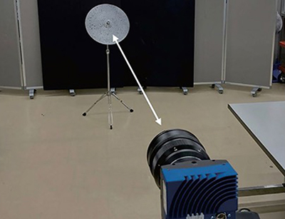 | ||
The Mikrotron camera capturing images during the first test |
To verify the effectiveness of the system, two sets of tests were conducted that documented the vibration frequencies of an oscillating cymbal and a steel box.
For the first test, a metal cymbal was observed as it freely vibrated after being struck with a wooden stick. Images were captured by the Mikrotron camera at a distance of four metres. The cymbal had been painted in a black and white speckled pattern for the camera to use as measurement points. Results showed peak frequencies corresponding to the natural frequencies of the cymbal. Vertical velocity components were stronger at the edge of the cymbal, while those around the centre vibrated weakly.
In the second test, an industrial steel box was forcibly vibrated by setting it on a vibration testing machine. As per the cymbal, the box was painted in a black and white speckled pattern. One of the findings was that, although all points were vibrating at the same peak frequency as the testing machine, the amplitudes distributed on the top region of the box were larger than those distributed on the bottom. This type of data collection is useful in structural analysis and mechanical defect identification.
In both tests, the vibration visualisation system was verified to accurately estimate full-field vibration responses at different levels of frequency, demonstrating similar results as standard contact sensors. Operators were able to directly observe the frequencies as visible image data by displaying them on a PC monitor.
For future work, the Hiroshima University researchers plan to improve the system to generate more accurate velocity fields. They also aim to assess more practical applications of the system, such as bridge VM and aided analysis for structural designs.