This is a new series of articles put together by BINDT’s Practitioner Committee to describe the principles of different NDT methods and techniques as an introduction to practitioners...
This article attempts to explain the basic concepts of industrial film radiography to those who have little knowledge of the subject; it is not intended to be an in-depth article.
Industrial radiography is one of the non-destructive testing (NDT) methods employed to ensure the integrity of a component, ie a casting or a weld. Radiography has been used as an NDT method to detect internal flaws in welds and castings.
The advantages of radiography include the following:
- It produces a permanent record
- It can be used on most materials
- It provides a direct image of flaws.
Radiography, due to the use ionising radiation, is very strictly controlled by legislation.
Radiation sources
There are two kinds of radiation source used to generate ionising radiation:
- X-rays: X-rays are generated by firing a beam of high-velocity electrons at a target material and the interaction (braking) of these electrons with the atoms in the target; and
- Gamma rays: gamma (γ) rays are produced when the atomic nuclei of a radioactive isotope disintegrate.
Both X-rays and gamma rays, although generated differently, are ionising radiations, cannot be detected by the human senses and are inherently dangerous.
Radiographic equipment
The choice of which source of radiation to use is dependent on many factors:
- The size and portability of the test part
- Power supply considerations
- Access limitations
- The stage of manufacture of the test part, for example in-service, on plant, etc
- The design and performance criteria of the test part for a given application
- How critical the structural integrity of the component to be tested is.
X-ray generators
The quantity of electrons is controlled by the milliamps (mA) of the X-ray set.
The quality/penetrating power is controlled by the kilovolts (kV) (the speed of the electrons).
Most conventional X-ray equipment is bulky, which restricts usage on site, in confined areas and being able to position and support the X-ray head to fully radiograph an item.
X-ray equipment is reliant on an electrical power supply being available.
High-energy radiography
There are two types of X-ray machine used in modern radiography for million-volt (MeV) radiography:
- Linear accelerators, commonly referred to as linacs; and
- Betatrons.
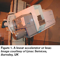 Linear accelerators (linacs)
The main advantage of a linac is the high energy employed and its output; most commercial linacs have energy values between 4 MeV and 9 MeV.
Betatrons
Betatrons work at similar energy values but at lower outputs.
Similarities
- High output/high energy, which allows for radiography of components with a thickness of up to 500 mm (linac) and 350 mm (betatron) approximately in carbon steel.
- The high energy employed means a wider thickness range can be radiographed, which means a subsequent reduction in the number of shots employed.
- The shape of the component plays a factor in radiographing heavy-wall sections due to scatter; the planer the shape the better the result.
- Even though the machines operate in the MeV output range, they are still greatly affected by the type of material required to be X-rayed.
Differences
- Betatrons are marginally larger than a conventional X-ray set and are more mobile compared to linacs.
- Linacs can very rapidly radiograph components with thicknesses of up to 250 mm.
Radioisotopes (gamma radiation)
Modern radioisotopes are artificially produced in a nuclear reactor by a process known as activation. Different types of isotope are available, as detailed in Table 1.
Table 1. Different isotopes
| Isotope | Applicable steel thickness | Equivalent X-ray kV | Half-life |
| Cobalt-60 (Co-60) | 40 to 200 mm | 1200 | 5.3 years |
| Iridium-192 (Ir-192) | 20 to 100 mm | 400 | 74 days |
| Selenium-75 (Se-75) | 10 to 40 mm | 217 | 120 days |
| Ytterbium-169 (Yb-169) | 1 to 15 mm steel | 145 | 31 days |
| Thulium-170 (Tm-170) | ≤5 mm steel | 80 | 128 days |
The source activity in the UK is generally identified in curies (Ci).
The activity is used by the radiographer to calculate exposure times using an exposure calculator; the source activity for a certain date is detailed on a decay chart supplied with the isotope.
Fundamentals of film processing[1]
The latent image produced on the film by exposure to gamma or X-rays is made visible and permanent by the processing procedure.
Processing is carried out under subdued light and the film is immersed in a developer solution, which causes the areas exposed to radiation to become dark. After development, the developer reaction is halted in a stop bath and then the film is fixed in a fixing bath. The purpose of fixing is to remove all the undeveloped silver salt of the emulsion, leaving the developed silver as a permanent image. The film is washed to remove the fixer and then dried.
Processing can be conducted either manually or by automatic film processing.
Radiographic interpretation
The standard with the contract specification will detail the minimum requirements that the radiograph will need to have achieved. The radiographer will calculate the essential parameters to produce a compliant radiograph, including:
- Density: the degree of darkening is usually described as density: the more radiation reaching the film due to thinner/less dense material blackens the film; the thicker/denser the material, the less radiation reaches the film, resulting in lighter areas on the film. Density is measured using either a calibrated densitometer or calibrated density strip.
- Contrast: the density difference between two adjacent areas of a film.
- Definition: the sharper the demarcation between two areas, then the more readily the eye will detect the difference in density.
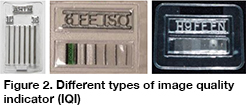
- Sensitivity: the sensitivity of a radiograph can be determined using image quality indicators (IQIs). There are several different types of IQI, including wire type and plaque/hole type, the use of which will be determined by the specification requirements.
Viewing of images
Radiographs should be viewed in a low ambient light.
The radiographic interpreter determines that the radiograph meets the criteria outlined in the approved radiographic procedure for both density and sensitivity and then views it to identify any defects that may exceed the acceptance criteria.
After the radiograph has been viewed and evaluated, a report will be produced giving the results of the sentencing plus all the relevant radiographic information.
Reference
- Radiography in Modern Industry, Second Edition, Eastman Kodak Company, X-Ray Division, Rochester, New York, USA, 1957.
Part 2 of this article will cover computed and digital radiography and will be published in the March 2022 issue of NDT News.
Comments by members
Comment by Abigail Smith
Houston, United States
Date 27/07/2024